Ingenieria asistida por ordenador
3 10 2011Os pongo un ejemplo de calculo de fatiga realizado con ansys versión clasica.
Datos:


(Go to Main Menu)
Preprocessor
Element Type
Add/Edit/Delete
Add
Structural & Solid & Quad 4 node 42 & OK
Material Props
Material Models
Structural
Linear
Elastic
Isotropic
EX = 210e5
PRXY = 0.3 & OK
Modeling
Create
Areas
Rectangle
By Dimensions
(Click X1 box) 0 (Click X2 box) 60
(Click Y1box) 0 (Click Y2 box) 1 & OK
Meshing
Mesh Tool
Click on the Lines Set button
Pick lines 2 & 4 & Apply
NDIV = 4
SPACE = -2 & Apply
Pick lines 1 & 3 & Apply
NDIV = 30
SPACE = -2 & OK
Click the Mesh Button
Pick All & OK
Solution
Analysis Type
New Analysis
Choose Transient & OK & OK
Sol’n Controls
Basic Tab
Time at end of loadstep: 10
Transient Tab
Choose Stepped Loading & OK
Define Loads
Apply
Structural
Displacement
On Lines
Pick line 4 & OK
Select All DOFs
Displacement Value = 0 & OK
Force/Moment
On Keypoints
Pick keypoints 2 & 3 & OK
Direction of Force/Moment: FY
Force/Moment Value: 50 & OK
Load Step Opts
Write LS File
Load step file number n: 1 & OK
Analysis Type
Sol’n Controls
Basic Tab
Time at end of loadstep: 20 & OK
Define Loads
Delete
Structural
Force/Moment
On Keypoints
Pick All & OK
Apply
Structural
Force/Moment
On Keypoints
Pick keypoints 2 & 3 & OK
Direction of Force/Moment: FY
Force/Moment Value: -50 & OK
Load Step Opts
Write LS File
Load step file number n: 2 & OK
Analysis Type
Sol’n Controls
Basic Tab
Time at end of loadstep: 30 & OK
Define Loads
Delete
Structural
Force/Moment
On Keypoints
Pick All & OK
Apply
Structural
Force/Moment
On Keypoints
Pick keypoints 2 & 3 & OK
Direction of Force/Moment: FY
Force/Moment Value: 74.5 & OK
Load Step Opts
Write LS File
Load step file number n: 3 & OK
Analysis Type
Sol’n Controls
Basic Tab
Time at end of loadstep: 40 & OK
Define Loads
Delete
Structural
Force/Moment
On Keypoints
Pick All & OK
Apply
Structural
Force/Moment
On Keypoints
Pick keypoints 2 & 3 & OK
Direction of Force/Moment: FY
Force/Moment Value: -74.5 & OK
Load Step Opts
Write LS File
Load step file number n: 4 & OK
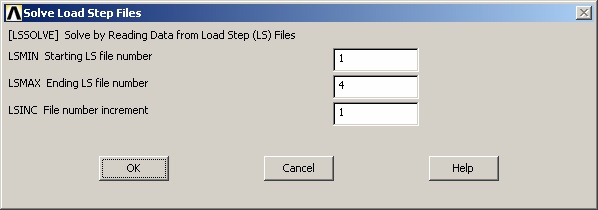
Solve
From LS Files
Starting LS file number: 1
Ending LS file number: 4
File number increment: 1 & OK

(Go to Main Menu)
General Postproc
Read Results
By Pick
Select Set 1 & Read & Close
Steps to perform the Fatigue Analysis
Definitions used in performing a fatigue analysis:
Location: a node in the model for which fatigue stresses are to be stored.
Event: a set of stress conditions that occur at different times during a unique stress cycle.
Loading: one of the stress conditions that is part of an event.
(Go to Main Menu)
General Postproc
Fatigue
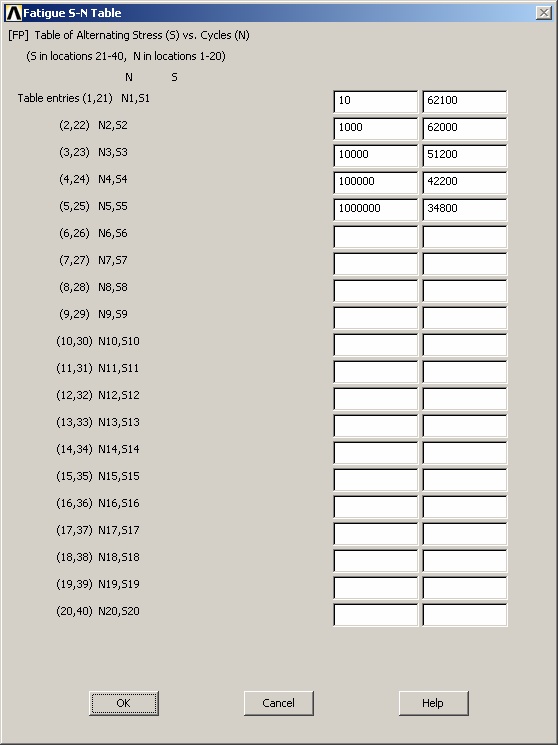
Property Table
S-N Table
(Click N1) 10 (Click S1) 62.1e3
(Click N2) 1000 (Click S2) 62.0e3
(Click N3) 10000 (Click S3) 51.2e3
(Click N4) 100000 (Click S4) 42.2e3
(Click N5) 1000000 (Click S5) 34.8e3

Stress Locations
NLOC = 1
NODE = 65 (node along the surface at the fixed end of the beam
TITLE = Fixed End & Apply
NLOC = 2
NODE = 54 (node along the surface in the middle of the beam)
TITLE = Middle & Apply
NLOC = 1
NODE = 32 (node along the surface at the free end of the beam)
TITLE = Free End & OK
Store Stresses
From rst File
NODE: 65
Event: 1
Loading: 1 & Apply
NODE: 54
Event: 1
Loading: 1 & Apply
NODE: 32
Event: 1
Loading: 1 & OK
Read Results
By Pick
Select Set 2 & Read & Close
Fatigue
Store Stresses
From rst File
NODE: 65
Event: 1
Loading: 2 & Apply
NODE: 54
Event: 1
Loading: 2 & Apply
NODE: 32
Event: 1
Loading: 2 & OK
Read Results
By Pick
Select Set 3 & Read & Close
Fatigue
Store Stresses
From rst File
NODE: 65
Event: 2
Loading: 1 & Apply
NODE: 54
Event: 2
Loading: 1 & Apply
NODE: 32
Event: 2
Loading: 1 & OK
Read Results
By Pick
Select Set 4 & Read & Close
Fatigue
Store Stresses
From rst File
NODE: 65
Event: 2
Loading: 2 & Apply
NODE: 54
Event: 2
Loading: 2 & Apply
NODE: 32
Event: 2
Loading: 2 & OK
Assign Events
NEV = 1
CYCLE = 500000
TITLE = Load 1 & Apply
NEV = 2
CYCLE = 5000
TITLE = Load 2 & OK
Calculate Fatig & OK
Results:
Location: 1 Node 65 at the fixed end.
The combination of event 2, load 1 and event 2, load 2 produces an alternating stress intensity of
55744 N/cm2. The spring was subjected to 5000 cycles while from the S-N Table, the maximum
number of cycles allowed at that stress intensity is 3595. The partial usage value, 1.39063, is the ratio
of cycles used/cycles allowed.
The combination of event 1, load 1 and event 1, load 2 produces an alternating stress intensity of
37412 N/cm2. The spring was subjected to 500,000 cycles while from the S-N Table, the maximum
number of cycles allowed at that stress intensity is 421,300. The partial usage value, 1.18669, is the
ratio of cycles used/cycles allowed.
The Cumulative Fatigue Usage value is sum of the partial usage factors (Miner’s rule).
Autors: Nyquist / Haghighi