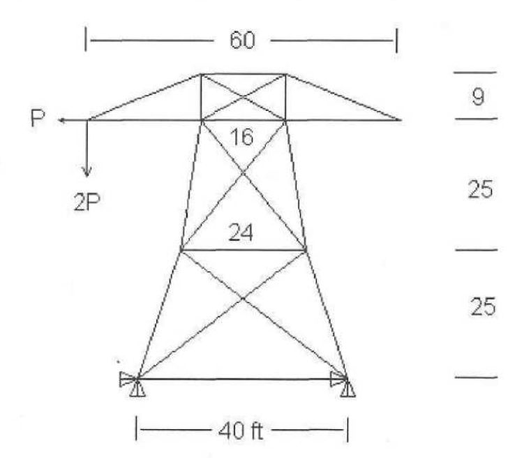
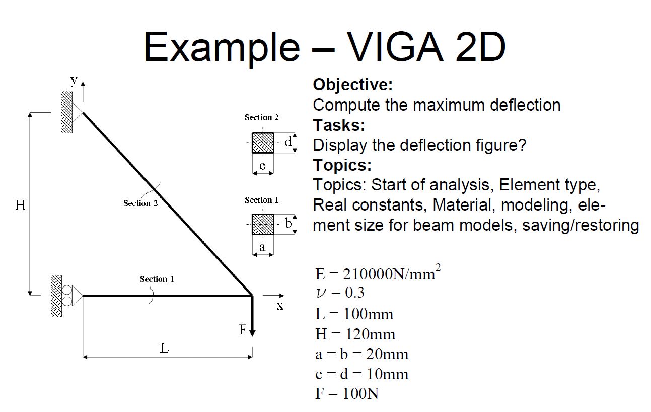
Os planteo el listado del primer ejemplo para que podais realizarlo en la version de ansys 12.1
/BATCH
/COM,ANSYS RELEASE 13.0 UP20101012 19:41:47 09/10/2012
/input,menust,tmp,»,,,,,,,,,,,,,,,,1
/GRA,POWER
/GST,ON
/PLO,INFO,3
/GRO,CURL,ON
/CPLANE,1
/REPLOT,RESIZE
WPSTYLE,,,,,,,,0
/PREP7
et, 1,beam3
r,1,400,13330,20
r,2,100,833,10
!*
MPTEMP,,,,,,,,
MPTEMP,1,0
MPDATA,EX,1,,2100000
MPDATA,PRXY,1,,0.3
K, ,,,,
K, ,100,,,
K, ,0,120,,
LSTR, 1, 2
LSTR, 2, 3
TYPE, 1
MAT, 1
REAL, 1
ESYS, 0
SECNUM,
TSHAP,LINE
!*
TYPE, 1
MAT, 1
REAL, 1
ESYS, 0
SECNUM,
TSHAP,LINE
!*
CM,_Y,LINE
LSEL, , , , 2
CM,_Y1,LINE
CMSEL,S,_Y
!*
!*
CMSEL,S,_Y1
LATT,1,1,1, , , ,
CMSEL,S,_Y
CMDELE,_Y
CMDELE,_Y1
!*
CM,_Y,LINE
LSEL, , , , 1
CM,_Y1,LINE
CMSEL,S,_Y
!*
!*
CMSEL,S,_Y1
LATT,1,2,1, , , ,
CMSEL,S,_Y
CMDELE,_Y
CMDELE,_Y1
!*
FLST,5,1,4,ORDE,1
FITEM,5,2
CM,_Y,LINE
LSEL, , , ,P51X
CM,_Y1,LINE
CMSEL,,_Y
!*
LESIZE,_Y1, , ,1, , , , ,1
!*
FLST,5,1,4,ORDE,1
FITEM,5,1
CM,_Y,LINE
LSEL, , , ,P51X
CM,_Y1,LINE
CMSEL,,_Y
!*
LESIZE,_Y1, , ,1, , , , ,1
!*
FLST,2,2,4,ORDE,2
FITEM,2,1
FITEM,2,-2
LMESH,P51X
!*
ANTYPE,0
FLST,2,1,3,ORDE,1
FITEM,2,3
!*
/GO
DK,P51X, , , ,0,UX, , , , , ,
FLST,2,1,3,ORDE,1
FITEM,2,1
!*
/GO
DK,P51X, , , ,0,ALL, , , , , ,
FLST,2,1,1,ORDE,1
FITEM,2,2
!*
/GO
F,P51X,FY,-100
FINISH
/SOL
/STATUS,SOLU
SOLVE
FINISH
/POST1
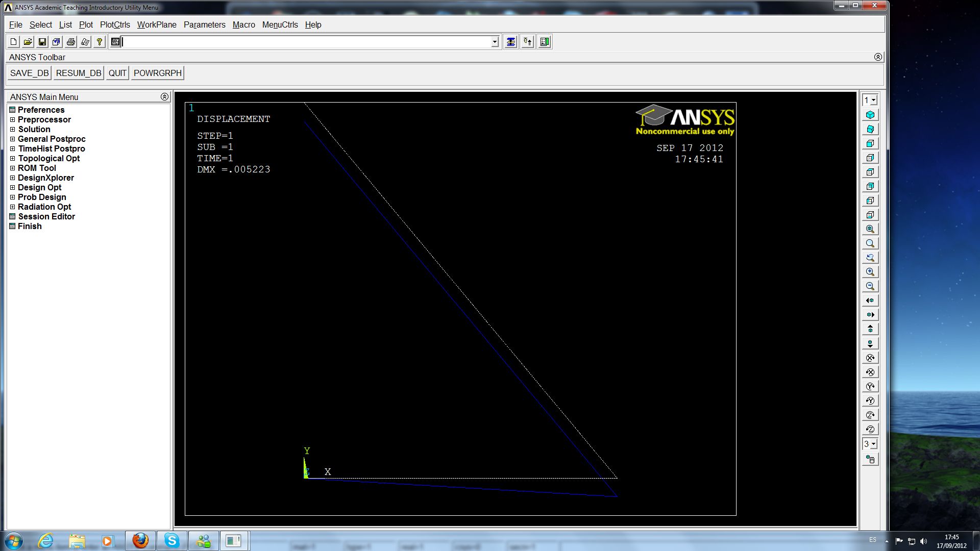
PLDISP,2
Las imagenes que salen son: