Tecnologías avanzadas de fabricación
20 03 2013Os pongo un liknk interesante de fabricación aditiva.
Categories : Tecnologia de Fabricación de Prototipos/Rapid prototyping
Os pongo un liknk interesante de fabricación aditiva.
Pagina interesante.

La impresión en 3D ha comenzado una revolución en la industria dental y de prótesis.
¿Veremos trasplantes de órganos imprimidos próximamente?
Quizás la aplicación más perturbadora (en el buen sentido) de la impresión 3D en el mundo de la medicina es “bioprinting”-la producción de órganos humanos para trasplante.
La tecnología implica la creación de tejidos y órganos de reemplazo que se imprimen capa por capa en una estructura tridimensional. Las piezas se fabrican a partir de material genético del receptor de órganos, y precisamente coincide con el tejido u órgano que van a sustituir. Pensad en esto: la piel, tráquea, vejigas, y las estructuras más complejas, como corazones, podrán imprimirse con un clic de ratón de ordenador.
Dado que estos órganos o tejidos impresos se fabrican a partir del propio paciente hay poco riesgo de una respuesta inmune, lo que disminuye la necesidad de utilizar los fármacos inmunosupresores, lo que a su vez mejora la calidad de vida del paciente que no se verá obligado a automedicarse de por vida.
Los avances en bioprinting han ido aumentando cada vez con mayor rapidez. Al igual que la carrera para llegar a la luna en una época anterior, el objetivo de bioprinting apareció como un objetivo muy lejano pero alcanzable, y el primer anuncio de bioprinter 3D fue desarrollado en 2009 por una compañía llamada bioprinting Organovo.
La compañía instalada en San Diego ha firmado un acuerdo de colaboración con varias compañías farmacéuticas, como Pfizer, y las principales instituciones de investigación, incluyendo la Harvard Medical School y el Consorcio de Stanford para la Medicina Regenerativa. Su principal mercado son las instituciones académicas para la investigación de enfermedades y las compañías farmacéuticas para las pruebas de medicamentos, aunque la compañía está buscando en los hospitales sus posibles futuros clientes.
Hasta la fecha, Novogen imprime sencillos tejidos como vasos de la piel, parches de músculo cardiaco, y sangre, aunque la compañía prevé imprimir órganos sólidos como el corazón y el hígado dentro de una generación.
Otro proyecto de 3D bioprinter también se está llevando a cabo en Wake Forest. En 2003, el Dr. Atala y sus colegas publicaron este trabajo en Nature Biotechnology demostraron que sería factible diseñar riñones en miniatura, y estos riñones experimentales demostraron ser funcionales, capaces de filtrar la sangre y producir y diluir la orina. Wake Forest en la actualidad ha conseguido diseñar modelos aún más sofisticados de estos riñones en miniatura. El objetivo es hacer que estos riñones funcionen a mayor tamaño al igual que conseguir otros órganos sólidos como el corazón y el hígado, o el útero.
“Otras aplicaciones que también han demostrado ser prometedoras son el oído, los músculos y la interfaz del cartílago-hueso”, dice el Dr. Atala.
Si algunos pueden hacer un arma o un coche con una impresora 3D, ¿Por qué no hacerte un vestido tan ajustado a tus medidas que te quede como un guante? Es la próxima revolución.
Desde hace dos años no dejan de salir noticias sobre lo que se puede hacer con una impresora 3D. Su filosofía es similar a las de toda la vida, sólo que aquí usan nuevos materiales, en general plásticos, en vez de papel. Y, capa a capa, van dando forma a un nuevo objeto.
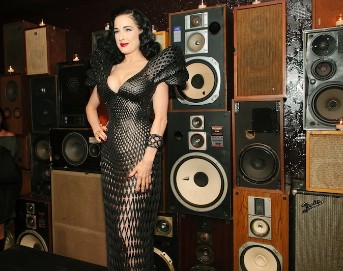
El último es un espectacular vestido que los diseñadores Michael Schmidt y Francis Bitonti han hecho para la reina del burlesque Dita Von Teese. A tenor de las fotografías que se hizo en el hall del hotel Ace de New York esta semana, le queda como un guante. No le hizo falta ningún arreglo. Otra cosa es que se le pudiera dar alguna puntada más.
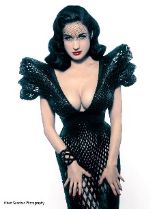
El «vestido de Dita», así lo han bautizado, cuenta con casi 3.000 piezas únicas, lo que lo convierte, dicen sus creadores, en el primero completamente articulado que se imprime con una de estas nuevas impresoras. También permitían que el traje se ajustara perfectamente a las formas de la diva. Los diseñadores se aprovecharon de la tecnología para tomar las medidas exactas de la Von Teese y, con esos datos, dejaron trabajar a la impresora.
Los diseñadores contaron con la empresa Shapeways para imprimir el vestido con capas de nylon para hacer hasta 17 grandes piezas, como en las antiguas armaduras. Después lo entintaron en negro y le dieron un laqueado. Por último, y para dar aún más glamour y exclusividad a esta creación, superpusieron unos 12.000 cristales de Swarovski.
En un guiño a la ciencia, el patrón del vestido sigue lo que se llama la sucesión Fibonnacci. Se tata de una secuencia de números naturales que empiezan con el 0 y el 1 y en la que el siguiente es siempre la suma de los dos anteriores. Planteada por un matemático italiano en el siglo XIII, es un patrón que se observa en la naturaleza (la distribución de las ramas de los árboles, por ejemplo) y tiene aplicaciones en informática.
Con el vestido de Dita, los diseñadores quieren mostrar las posibilidades que las impresoras 3D tiene para el diseño en el futuro más inmediato. Usadas ya para crear tejidos humanos, armas y hasta una casa, el presidente Obama dijo en un reciente discurso que estas máquinas serán las protagonistas de la nueva revolución. También en la ropa que llevaremos.
No es nada descabellado. En la reciente Semana de la Moda de París, el creador Iris van Herpen llevó hasta la pasarela su colección Voltage, una serie de 12 vestidos realizados con impresoras 3D. No pasará mucho tiempo en que esas impresoras puedan comprarse, ya las hay por menos de 1.000 euros, y con el patrón en formato digital, imprimr en casa lo último de la moda. Seguro que igual que se descargan películas o música de internet, descargaremos la ropa.
Aquí podéis ver parte del proceso de creación
* Gracias a The Verge por descubrirme esta fascinante historia.
funete: http://www.elmundo.es/yodona/blogs/techtaciones/2013/03/08/hazte-tu-vestido-a-medida-con-una.html
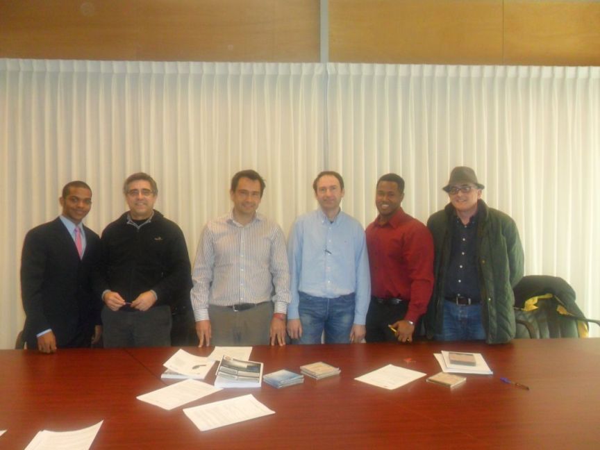
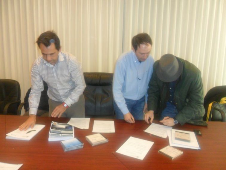
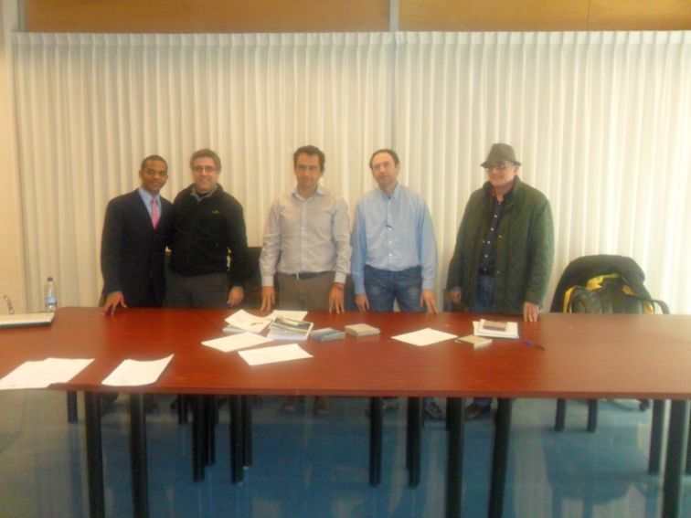
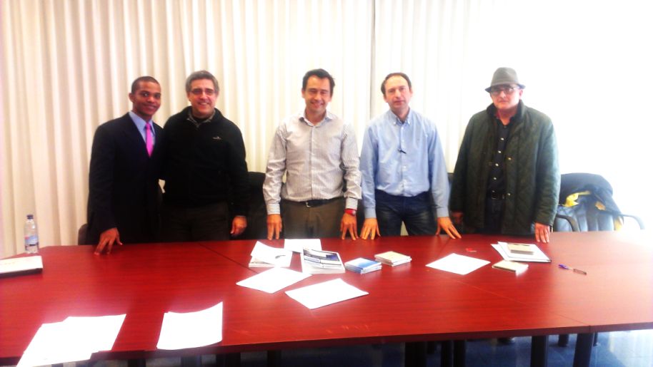
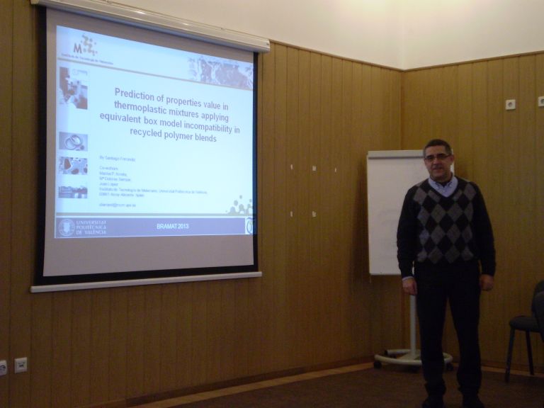
Nuestar estancia en el congreso BRAMAT 2013, permitó presentar una ponencia interesante.
por Juan Castromil @castromil el día 03/03/2013

Mientras vivimos la prehistoria de las impresoras 3D algunos visionarios ya están trabajando en los objetos 4D. A los ya clásicos largo, alto y ancho se le suma la cuarta dimensión, el tiempo. Por extraño que parezca se trata de objetos diseñados para cambiar de forma según pasa… el tiempo -y no precisamente por desgaste o rotura- sino para cumplir una función específica.
Este nuevo tipo de objetos que se adaptarán al entorno cambiado su forma como si estuviesen programados, han sido presentados por Skylar Tibbits del MIT Self Assembly Lab en la conferencia TED. En el ejemplo mostrado durante la presentación era una pequeña tubería que cambiaba de forma al ser introducida en agua. En este caso, el agua actúa como una especie de catalizador para activar el cambio de forma del objeto, pero esto puede ocurrir por otros muchos motivos.
Es como si la fabricación/impresión de objetos 4D sólo fuese la mitad del proceso. La otra mitad finaliza cuando el objeto adopta la forma final para su función. Estos materiales inteligentes pueden suponer una revolución en el futuro, siendo capaces de autorepararse cambiando de forma al detectar un fallo.
[vimeo 58840897 w=400 h=300]
+ info | wired
fuente: http://blogs.20minutos.es/clipset/el-futuro-de-la-impresion-3d-son-los-objetos-4d/
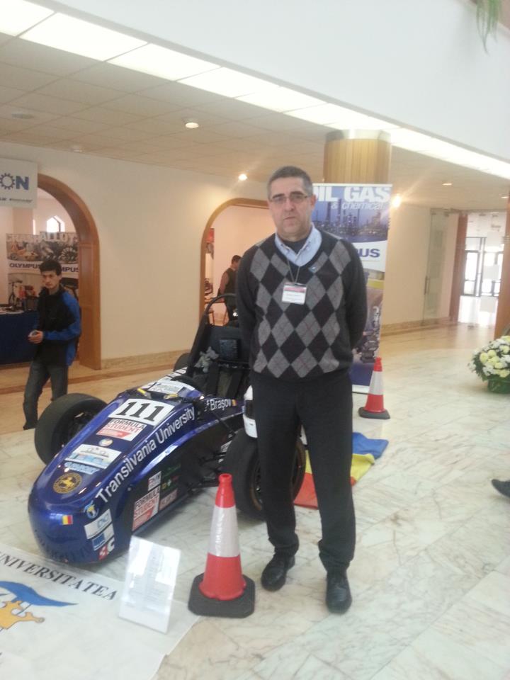
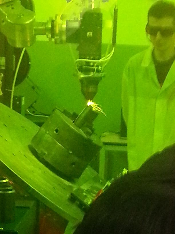
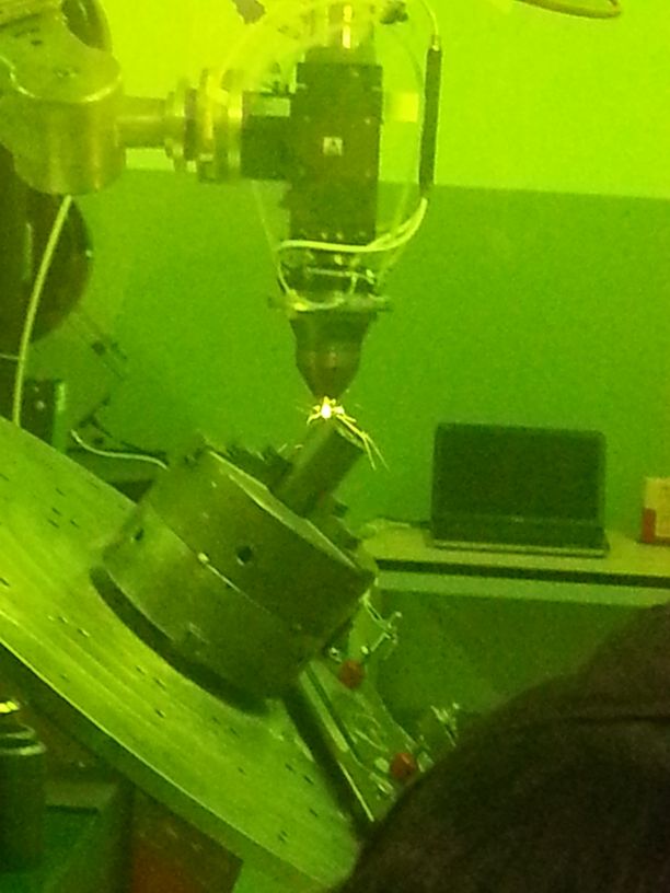
En el Instituto Tecnológico de Transilavania de Brasov.
[politube2]56376:450:273[/politube2]
En el Instituto Tecnológico de Transilavania de Brasov.
Boligrafo tridimensional.
The first commercial Laminated Object Manufacturing (LOM) system was shipped in 1991. LOM was developed by Helisys of Torrance, CA. The main components of the system are a feed mechanism that advances a sheet over a build platform, a heated roller to apply pressure to bond the sheet to the layer below, and a laser to cut the outline of the part in each sheet layer. Parts are produced by stacking, bonding, and cutting layers of adhesive-coated sheet material on top of the previous one. A laser cuts the outline of the part into each layer. After each cut is completed, the platform lowers by a depth equal to the sheet thickness (typically 0.002-0.020 in), and another sheet is advanced on top of the previously deposited layers. The platform then rises slightly and the heated roller applies pressure to bond the new layer. The laser cuts the outline and the process is repeated until the part is completed. After a layer is cut, the extra material remains in place to support the part during build.
")
Laminated Object Manufacturing (LOM)
Fuente: http://www.custompartnet.com/wu/laminated-object-manufacturing
Lectura de tesinas del Máster CAD-CAM-CIM.